
| Home Archive catalogue Bio of Turing More about Turing Codebreaking Artificial Intelligence Computer history Photo gallery Books on Turing Cambridge archive Links Copyright
|
The Alan Blumlein Homepage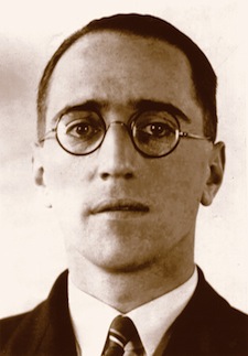
This homepage by David Clayden, MIEE. Blumlein and the Automatic Computing EngineThe ACE Pilot Model project started in NPL's Radio Division with a team of mathematicians and engineers drawn from Mathematics Division, Radio Division and Electricity Division. The engineers of Radio Division had long experience of radio receiver and transmitter design. In 1947, the team was joined by Ted Newman from EMI (Electric and Musical Industries) Research Laboratories. At EMI Newman had gained extensive experience of radar and television camera design. David Clayden followed Newman from EMI to Radio Division in September 1947. At that time the logic design of the Pilot Model had been settled by the members of the Mathematics Division, including Alan Turing, Jim Wilkinson and Donald Davies, and a decision had been made that the main store would be mercury delay lines. Newman, the main architect of the circuit design of the Pilot Model, introduced some of the practices common at EMI and due to the brilliant electronic engineer Alan Blumlein. Before the war Blumlein produced 128 patents, many concerning the EMI television system. Newman worked on radar with Blumlein during the war. The Blumlein style circuits that Newman designed for the ACE Pilot Model were highly advanced for the time. Alan Dower BlumleinAlan Dower Blumlein was born in 1903 in London. His father, a mining engineer, was a naturalised British subject from Germany. Alan was awarded a first class BSc degree following education at Highgate School and City and Guilds College in 1923. He joined International Western Electric Corp and Standard Telephones and Cables in 1924, and was involved in long distance telephonic communication in Europe. He was awarded a prize for his contribution at the age of 23. In 1929 Blumlein started work for the Columbia Graphophone Company. Within a short time he produced an advanced moving coil wax cutting machine for cutting gramophone record masters. He also designed a moving coil microphone. About 1930 he became interested in stereophonic recording and reproduction. His work resulted in an outstanding patent on the subject and a new method of cutting stereo disks. About this time he developed some circuit design principles to make circuit behaviour less dependent on valve characteristics. The current passed by a valve with a fixed bias varied from valve to valve so much that sometimes, on a production line, valves were selected for particular characteristics. Blumlein developed the principle of defined current circuits in which the valve's current was defined either by a cathode resistance to a considerably lower potential, or by employing negative feedback. These principles together with the long-tailed pair were patented in about 1936. Upon these principles were built other circuit ideas including the wide-band DC coupling. During the war these principles survived the rigours of quantity production in a factory under military specifications and, after the war. were used in the design of the ACE Pilot Model, the Deuce and the ACE. Before the opening of the London television station at Alexandra palace in 1936, Blumlein's activities were devoted to the engineering of the 405 line system. At this time scanning was performed by mechanical spinning disks. In 1931 the Gramophone Company (HMV) merged with the Columbia Graphophone Company to form Electric and Musical Industries. This started a major research into the design and manufacture of vacuum cathode ray tubes. This work lead on to the development of the iconoscope tube for cameras. This effort was crowned by the outside televising of the coronation procession in 1937, linked by an eight mile cable to the transmitter. A new type of aerial was needed for this and Blumlein invented the resonant slot aerial. In 1939 the Company developed a 60 MHz radar patented by Blumlein and E L C White. Blumlein was involved with a visual display for the stereo sound locators in use for gun laying. By 1940 it was delivering airborne interception radar for Beaufighters. In 1941 work began on H2S, a radar system to aid bombers to find their target. It was during the testing of this equipment that Blumlein, Browne and Blythen of EMI Research Laboratories together with three TRE staff were killed in a disastrous air crash. In spite of this H2S became operational in 1943 and some units were allocated to the detection of enemy submarines. This made a substantional contribution to the Battle of the Atlantic. After the crash, Ted Newman, who had joined the Laboratory at about the beginning of the war, became responsible for the further development of H2S and other military projects. After the war he was involved in the development of television cameras. David Clayden, who joined the Laboratory in 1941, also absorbed Blumlein's design principles, and both Newman and Clayden employed these principles in the design of the ACE Pilot Model and the ACE when they moved to the Radio Division of NPL in September 1947. Blumlein was a remarkably prolific, versatile and inventive engineer. His capacity for hard work was immense and he often worked into the small hours, seven days per week. In 1933 he married Doreen and had two sons, Simon and David. It was Simon who gave the annual Blumlein lecture at the IEE in April 2000. Although Alan was killed at the age of 38, his contributions to electronic engineering embraced many aspects of the discipline. The breadth of these contributions can be gauged by the fact that he produced 128 patents as well as writing two IEE papers and some popular papers in Wireless World. For further information see 'A D Blumlein - Engineer Extraordinary' by R W Burns in the Engineering, Science and Education Journal of the IEE for February 1992. The author is indebted to Professor Burns for information abstracted from this article. The Long-Tailed PairConventional valve amplifiers traditionally had a bias resistor connected between a valve's cathode and earth (zero volts), the grid of the valve being biassed to earth. The value of this resistor, a few hundred ohms, was chosen so that the cathode worked at a few volts above earth, thus providing an appropriate grid bias voltage corresponding to the valve's advertised characteristics at the desired working current. (Calculating the value of the resistor involved Ohm's Law.) An undesirable feature of this arrangement is that the valve current can vary from one valve to another by a considerable margin, depending on the characteristics of the particular valve. This feature can be avoided by increasing the value of the resistor to a few thousand ohms and connecting it, not to earth, but to a negative voltage of, say, -100 volts. The current through the resistor and the valve is then determined by this voltage and the value of the resistor, the valves operating clear of grid current. If the resistor is 10000 ohms then the current is close to 10 milliamps, the characteristics of the valve having little influence. This high-value resistor is known as a long-tail. This principle can be extended by having two valves (triodes or pentodes) working side by side, with their cathodes connected together and sharing the current from one long-tail resistor. Their anodes are connected to some suitable positive voltage, say +200 volts. The way in which the two valves share the current is then controlled by the relative voltage of the two grids. The input signal is connected to one of the grids, while the other one is typically connected to a fixed potential. If one grid is 10 volts above the other, then all the current goes to its anode. Thus it is possible to switch all the current from one valve to the other (or, at smaller signal amplitudes, to create a balanced push-pull amplifier). This arrangement is the long-tailed pair. One double triode valve may be used in place of two triodes. Blumlein patented the long-tailed pair in 1936. There are two distinct functions of the long-tailed pair. It was first developed as a small signal amplifier producing a well balanced push-pull pair of outputs from the two anodes. The other function is as a switch where all of the cathode current is switched to one or other anode (the anode current of one valve being reduced to zero). As an amplifier it was used at both audio frequency and radio frequency. As a switch it was used in television and radar circuits. (In transistor circuits the same functions can be obtained by using emitter coupled circuits.) These functions were used extensively in the ACE Pilot Model and its decendants. Switching advantages of the long tailed pair To achieve an AND gate it was possible to feed the anode current of a valve to the cathode of another, the lower valve having its cathode at about -200 volts and being fed current from -300 volts. This provided two input grids supplying signals which were used for various logical operations. A contending circuit technology used in some computers at that time was the pentode with both the grid and the suppressor being used as signal inputs. Although this circuit provides an AND gate in one valve there are two important disadvantages of the circuit. Firstly the action of the suppressor is to divert the cathode current from the anode to the screen. Unfortunately in general the maximum screen dissipation is much lower than that of the anode, in the range 20% to 30% of the anode rating. As a consequence the cathode current has to be limited to about a quarter of the valve's normal current, and the anode load resistance has to be increased by a factor of four to achieve the same output signal size. This increases the switching time in proportion. The second disadvantage is that the suppressor provides a much lower gain than the first grid so that its signal amplitude needs to be several time larger. The extent of this depends on the valve type, but the machines of the 1950's which used this technology ran at a rate of about a tenth of a million bits per second. Blumlein's PatentsThe dates given below are the dates that the patents appear in the British Library index. The date of granting the patent is usually about two years earlier. Most of Blumlein's patents were written in the years 1933 to 1940. At this time he was working in the Research Department of Electric and Musical Industries at Hayes, Middlesex. However some patents in 1933 in the name of EMI have been included in this list because it is most likely that Blumlein was involved at that time. The list is divided by year corresponding to the index books in the British Library. Some relevant patents in the name of members of Blumlein's team have been included. The patent numbers follow the brief description. The following abreviations are used: CRT = Cathode ray tube, RF = radio frequency, AF = audio frequency, HF = high frequency 1933 Oct to 1934 Dec 1934 Dec to 1936 Jan 1936 Jan to 1937 Feb 1937 Feb to 1938 Mar 1938 Mar to 1939 Feb 1939 Feb to 1940 Apr Comments The long-tailed pair |
